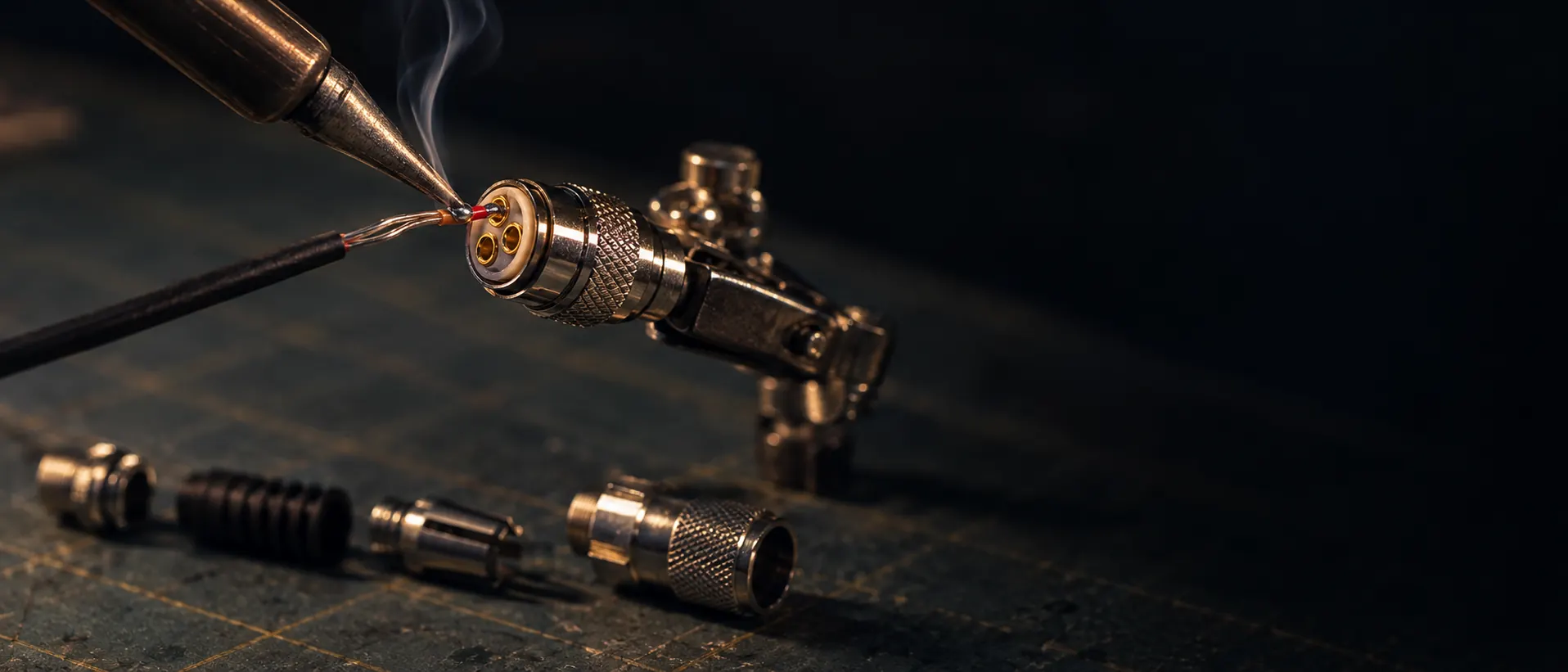
Soldering & repairing a 3-pin LEMO connector
Terminating or repairing a 3-pin LEMO for a Sennheiser SK bodypack is fiddly, exacting work. Here's the pinout, the right parts and the key steps, with a bench sheet you can print and work from.
What you'll need
Tools
- Temperature-controlled iron with a fine conical or bevel tip
- Helping-hand or bench vice
- Precision pliers/Fine-tip tweezers
- Side cutters
- Good light and some magnification
- Solder sucker
- LEMO drive tool, DCL.91.516.5TK
Consumables
- Thin rosin-core solder (0.5 mm or finer)
- Flux, to help the fine joints take cleanly
- Heat-shrink in a couple of sizes
- Liquid electrical tape
- The LEMO connector with its strain-relief boot
Assembly, step by step
These are LEMO's official mounting steps, as supplied in July 2026. Where you see a note, those are Richard's personal touches from the bench. Where his habits and LEMO's figures differ, follow LEMO's.
-
01
LEMO · Official step
Boot and screw ring on first
Slide the bend relief (GMF.00.018.DN) and the screw ring (FVB.00.455) onto the cable before anything else.
-
02
LEMO · Official step
Strip the outer jacket
Strip the outer jacket back 6 mm.
-
03
LEMO · Official step
Terminate the screen
Comb the screen back evenly over the jacket and slide the crimp ferrule (FVG.00.160.DN) over it. Crimp with the DPE.99.123.1K, 1 mm behind the edge of the ring.
Important -
04
LEMO · Official step
Remove the fillers
Cut away both white plastic fillers flush at the jacket.
-
05
LEMO · Official step
Prepare the conductors
Trim the conductors to 3 mm and strip 1 mm.
-
06
LEMO · Official step
Solder to the insulator
Solder the conductors to the insulator following the pinout, then clean the joints.
123Solder-cup side (rear view) · key at top
1Ground / screen
2Positive bias / power
3Audio signal
Sennheiser SK standard. Confirm against your mic and transmitter before soldering.
Important -
07
LEMO · Official step
Fit the insert carriers
Fit both split insert carriers, FVG.00.150.LN and FVG.00.151.LN.
-
08
LEMO · Official step
Seat in the outer shell
Slide the assembly into the outer shell. The anti-rotation tab must snap into the groove in the shell.
-
09
LEMO · Official step
Secure the screw ring
Apply a drop of Loctite 243 to the screw-ring thread, then tighten the ring carefully with the DCL.91.516.5TK spanner.
Warning -
10
LEMO · Official step
Glue the bend relief
Glue the bend relief to the outer shell to finish.
Warning
Choosing the LEMO connector
The 3-pin LEMO comes in three body variants, identical but for the cable clamp. Richard recommends the larger FVB.00.303.NLAE24, because it is the only variant the DCL.91.516.5TK drive tool fits. If your lav cable is thinner than 2.3 mm, build it up with heat-shrink (step 1) so the clamp still grips properly.
Pair it with the matching LEMO strain-relief boot, GMF.00.018.DN, which slides over the clamp to protect the cable exit and take the strain off the joints.
The assembly drive tool
Closing the connector and tightening the cable clamp needs LEMO's dedicated drive tool, a special driver that seats over the clamp nut.
There is no second drive tool. LEMO confirmed that the DCL.91.516.5TK is the only tool made for screwing the nut at the rear of these connectors; there is no smaller equivalent for the NLAE18 and NLAE13. For those two, LEMO instead points to a glueing option set out in their own mounting instruction. Confirmed by email, July 2026.
Tools & LEMO part numbers
Every LEMO part number for this job in one place. Where LEMO publishes a datasheet, the number links to it.
On the crimp die. The DPN.99.002.5K is a specialist item rather than a shelf product, quoted at AUD $621 ex-GST (February 2026; confirm current pricing before ordering). At that price it only makes sense if you are terminating these regularly. For occasional repairs, a good pair of fine crimpers and a careful hand will get you there.
The 3-pin LEMO pinout
Solder-cup side (rear view) · key at top
This is the standard arrangement for a Sennheiser SK 3-pin input. Confirm it against your specific microphone and transmitter before soldering. Bias arrangements vary between mic models, and the wrong pin means no audio or no power.
Wisycom: A note on the pinout
Wisycom's LEMO-fitted transmitters (the MTP40S and its relatives) have no single fixed pinout. What each pin carries depends on the MIC Mode selected in the transmitter menu. Two things follow from that, and both cost time on set.
The pin order itself is the familiar one: ground on 1, power on 2, audio on 3, the same as the table above. What changes is whether pin 2 is doing anything at all, and whether the audio line is carrying a bias voltage on top of the signal. A perfectly soldered lead can still be silent because the transmitter is in the wrong mode, so check the menu before reaching for the iron, and again before deciding the joint is at fault.
Pin 1 is ground in every mode, and the gain range is −60/40 dB throughout, so the choice is really about how the capsule gets its power: down the audio line as a bias, on its own conductor, or not at all.
If you need PTT, choose a two-wire mode. The full push-to-talk options (normal and muting) and the PTT LED indication are only offered in 2 wires and 2 wires + bias. The three modes that use pin 2 for power drop back to disable or no-data, and lose the PTT LED with them. That is a wiring decision as much as a menu one, so settle it before you cut the cable.
Values here follow Wisycom's published MIC Mode options. Firmware and models vary, so confirm against the manual for the transmitter in your hand before committing a joint.
Prefer it done right the first time?
Richard re-terminates lavs and builds cables for Perth crews
Re-terminating and maintaining lav rigs is part of running a location sound kit. If you'd rather hand it over, drop it off or post it and it comes back tested, with the price agreed up front.
Get in touchMore on repairs and custom builds.